User Guidance | Precautions for Using Microwave Radar Module
Release time:
2022-12-19 00:00
In recent years, with the development of radar technology and the strong demand for intelligence, microwave radar module has become one of the focuses of the semiconductor industry.
In 2018, Shenzhen MoreSense Technology Co., Ltd. launched a 5.8G microwave radar module product line, which has been widely used in smart lighting, smart home, smart home appliances, smart security, smart bathroom and other fields, with monthly shipments of more than 1 million pieces.
In the process of serving customers, MoreSense has accumulated rich experience in the application of microwave radar modules, and made some summaries of various usage problems and precautions that customers are concerned about.And today MoreSense intercepts some points to share.
01
Structural Design & Radar Module Installation Precautions
- The microwave signal will be strongly reflected when it encounters metal, which will introduce additional noise to the radar, and the metal will also change the radiation characteristics of the antenna, so that the sensing range changes, so special attention is required when installing the module.
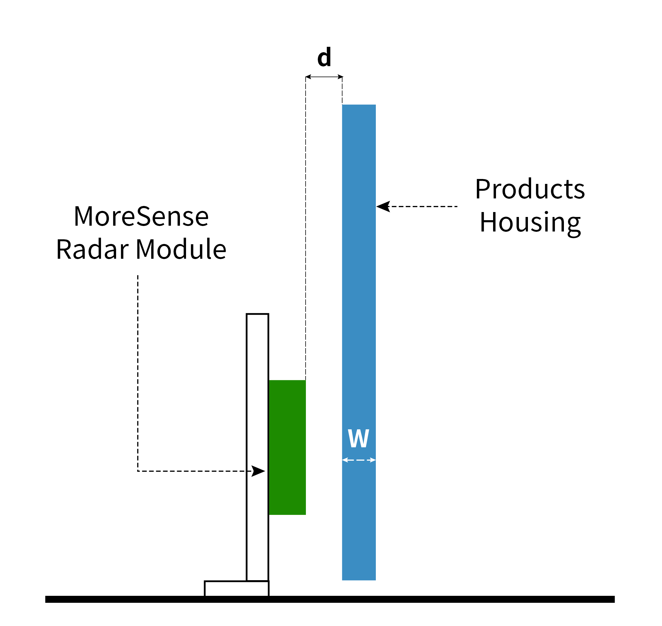
- When designing the product, the front of the antenna must not be covered by metal housings or parts.
-
Plastic or plexiglass and other occlusions are allowed, but the occlusion should not be close to the antenna, as shown in the figure below, it is recommended that the distance between the radar module antenna and the finished shell d>3.5mm;The optimal thickness of the housing is W<4mm (note: every 3mm increase in thickness, the sensitivity reduces by about 20%).

-
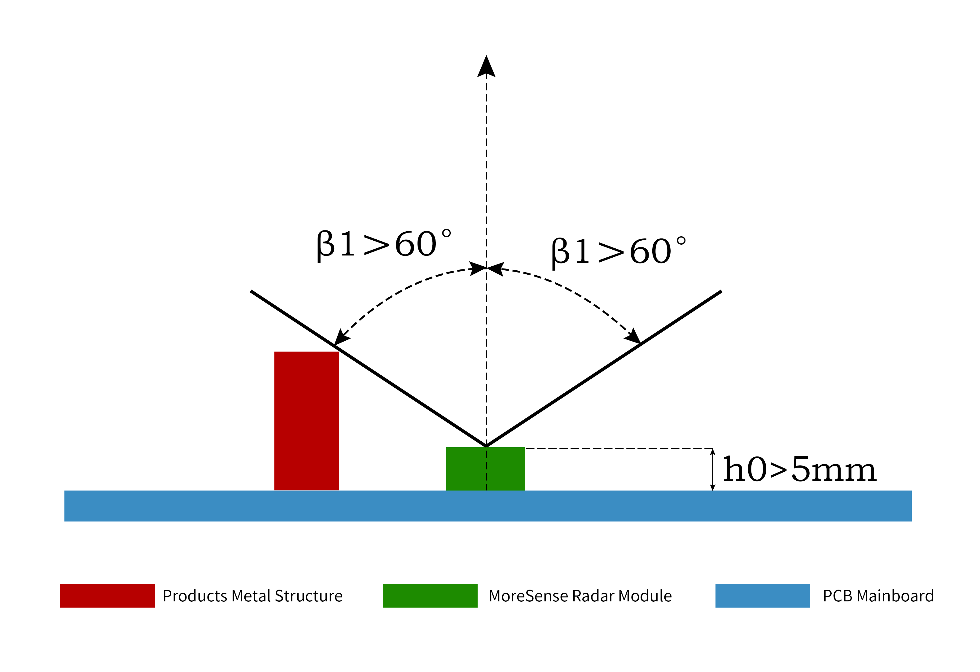
When the sensor is mounted on the finished product, if there is a metal structure due to the product characteristics and can not be avoided, pay attention to the metal structural parts which can not protrude too much, it is recommended that the components or metal structural parts and antenna radiation angle β1> 60 degrees (very important !!!) to avoid sensing blind spots, as shown in the figure below. It is recommended that the antenna plane of the radar sensor be raised above other nearby ground planes by h0>5mm.

2
Common Power Disturbances & External Component Interference
Notes
-
The power supply of the radar module needs to consider factors such as whether the power supply voltage is matched, whether the driving capability is sufficient, and the ripple size of the power supply. Low power supply voltage affects the signal amplitude, making the sensing distance closer; insufficient driving ability or large ripple makes the noise bigger, leading to continuous false triggering of the radar.
a. If the default voltage of the module is 5V and the auxiliary power supply voltage is >5.5V, an external LDO is required to stabilize the voltage to 5V.
b. If the operating current of the module is about 20mA, the auxiliary power supply should have more than 50mA driving capability.
c. Low frequency (<200Hz) ripple <50mV, high frequency (>500Hz) ripple <500mV.
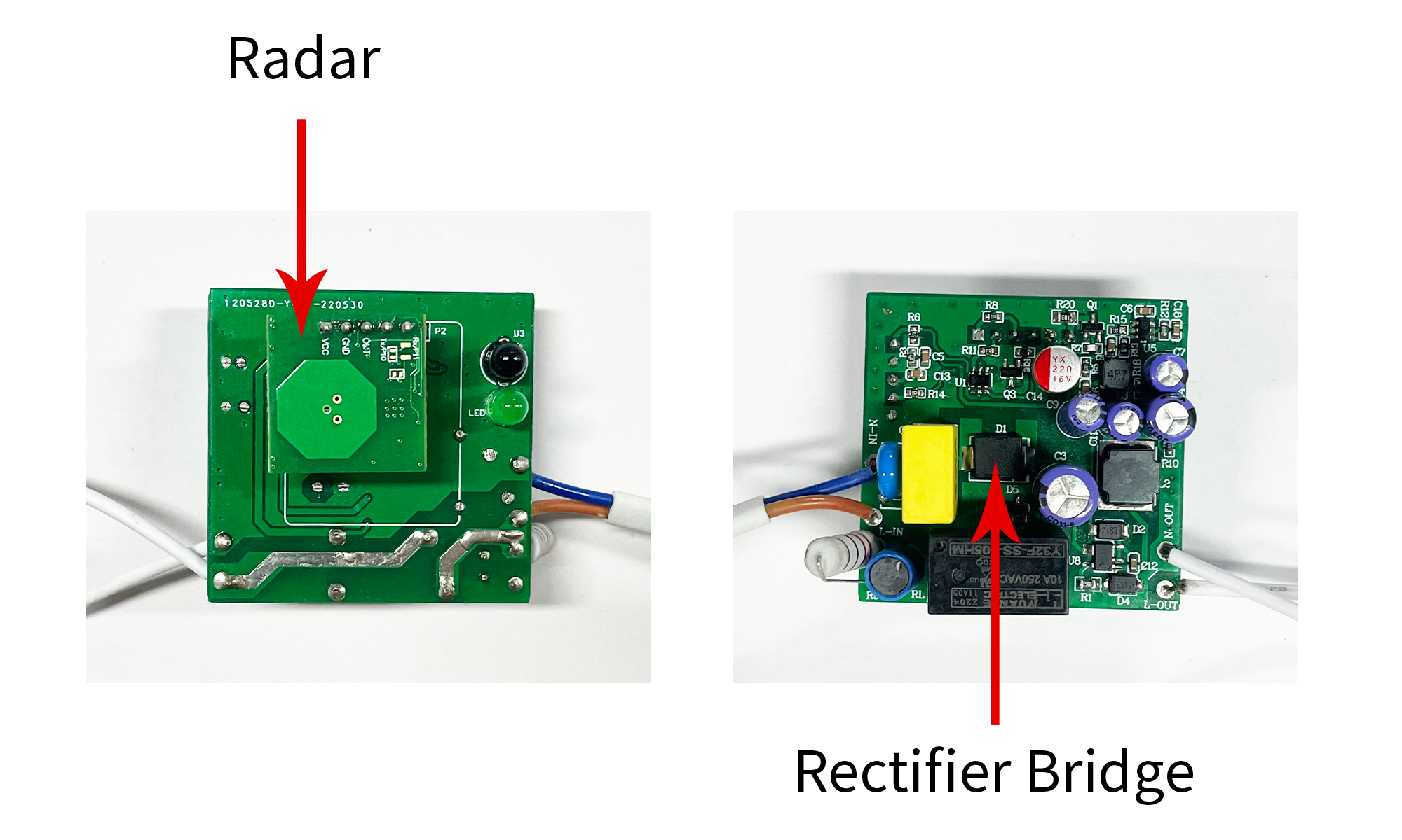
- The industrial frequency of the power supply is strong noise for the radar, and the influence of industrial frequency should be avoided as much as possible. The rectifier bridge of the power supply drive has the effect of frequency mixing, and the industrial frequency signal is easy to overlap with the radar signal, make sure that the radar module is far away from the rectifier bridge circuit, and the hardware and software can be processed separately as follows:
a. The power drive of products such as bulb light, T8 lamp which integrated with radar module, the radar will be placed in the place that the rectifier circuit away from the radar antenna position while designing products power supply ,in the overall structural design of a good shielding; shown in the following figure:

b. Software algorithms can filter the industrial frequency.For the scene of strong industrial frequency interference, it needs to use a specific software version;
-
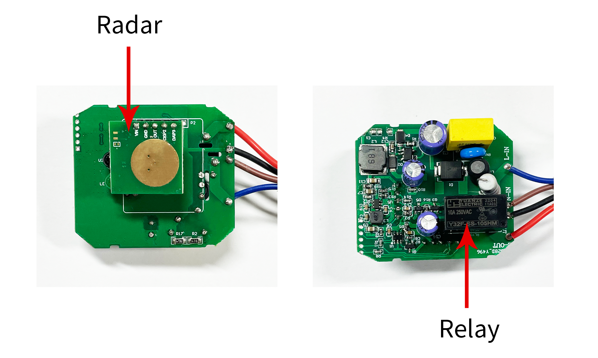
Relay on and off will form a strong perturbation to influence the radar signal. Relay on and off will produce large disturbances in the power supply, while the metal shrapnel movement of the relay itself is a Doppler interference, radar hardware and software need to do the corresponding processing.
a. When designing the product structure, put the radar sensor far away from the relay position, or do a good job of shielding on the structure, as shown below:

b. Terminal software need to do shielding for relay interference, ignoring the relay on and off the moment of the radar sensor signal.
-
The buzzer switch and the indicator light flashing affects the sensing signal ---- The buzzer switch disturbs the power supply, and the switch and the 5.8G signal will be mixed. The indicator light has similar problems, so it needs to be dealt with accordingly by the hardware and software:
a. Place the buzzer and switch away from the radar when designing the product structure;
b. The product software should block the interference and ignore the radar sensing signals when the buzzer switch and the indicator light are flashing;
3
Coexistence of Radar Sensors and WiFi/BT/NB etc.
Precautions
Stagger the space as much as possible, space out the IoT module antenna and radar antenna.
Stagger the time as much as possible, block the radar sensor's signal when the IOT module communicates.
Stagger the frequency as much as possible, by adjusting the frequency of the radar sensor to avoid the corresponding communication frequency.
4
Integrated Microwave Radar Module
Product Testing & Installation Precautions
Microwave sensing radar has a certain ability to penetrate walls such as thin wooden walls and glass walls,but not easy to penetrate solid brick walls.
When the radar sensors are densely distributed, in order to avoid mutual interference and false triggering, we should try to ensure that the radar antennas are parallel to each other, and avoid direct exposure to each other.
When the whole light is installed, try to ensure that the radar sensor lights are not less than 1.5m apart from each other; for aging test and other scenes that require dense distribution, ensure that there is more than 20cm spacing between the lights.
The sensing distance is measured under certain testing conditions such as the actual sensing distance and the whole light assembled height, the openness of the test site, the size of the testers (short, tall, fat and thin) and the pace of the direction.
Avoid embedding radar sensing products deep inside metal drums or metal cavities.
Doppler radar detects motion, try to avoid installing the radar sensor products in areas such as air conditioning vents to avoid vibration affecting the sensing effect.
When installing the finished product, try to avoid the radar antenna facing large metal equipment or pipelines.
5
A few keywords to keep in mind when applying microwave radar development and debugging
Gain and Sensing Threshold Self-Excitation Margin Bottoming
Gain and Sensing Threshold: Gain and sensing threshold are the most important parameters to determine the radar sensing distance, the two parameters need to be reasonably coordinated in order to achieve the ideal sensing effect, gain to realize the coarse tuning of the distance, sensing threshold to realize the fine tuning of the distance.
Self-Excitation: Self-excitation refers to the phenomenon that the radar module outputs sensing signals on its own without obvious interference from moving objects. There are various reasons for self-excitation, such as: the sensing threshold is set too low; the power supply is unstable and the ripple is too large; the buzzer, relay, etc. work to produce mechanical interference and power fluctuations; the motor, fan, air conditioning fan blade, etc. work impact.
Margin: the margin is in the process of debugging the radar, the parameters selected should leave enough tolerance for the back of the mass production, to prevent the radar from generating self-excitation in the limit cases, so it is necessary to bottoming the radar module to be able to work normally in the limit parameters (sensing threshold).
Bottoming: The process of obtaining the limit parameters of the radar module in the whole machine is called bottoming. The goal of bottoming is to obtain the sensing threshold at which the radar module starts to generate self-excitation at a fixed gain.
6
MoreSense has accumulated rich application experience and service insights in the process of radar promotion.
There are various fields which integrated with radar module, covering lighting, switches, home appliances, security, sanitary ware, etc., each field has a variety of different product categories and product structure, most of the one-on-one by the MoreSense to help customers debugging test, to the final delivery, to provide the full process of technical services and guidance.
Module series, currently in mass production of up to dozens of module types, matching customers with a variety of product structure and scene needs (please kindly check the MoreSense radar module catalog).
The number of customers served is up to 500+, the number of modules delivered in bulk is more than 1 million pieces per month, the stability and reliability have been verified by the large-scale market.
Recommended News


