


FAQ
Q
For final products that require networking, the following points should be noted when radar sensors and WiFi / BLE / NB coexist:
a. Stagger the space as much as possible, let the the distance of IOT module's antenna be away from the radar antenna.
B. Stagger as much as possible on the time, when the IOT module communicate please shield off the radar sensor signal.
c. Stagger the frequency as much as possible, by adjusting the frequency of the radar sensor to avoid the corresponding IOT module communication frequency.
Q
Buzzer switch and indicator light blinking have an effect on on the sensing signal.How do customer solve this issue?
Buzzer switch has disturbance to power supply and it will mix frequency with 5.8G signal together, the indicator light also has a similar problem. So we need to do the corresponding processing for modules' software and hardware:
a. Place the buzzer switch away from the radar when designing the product structure.
b. The product software is shielded against interference, ignoring the radar sensing signals when the buzzer switch and the indicator light are flashing.
Q
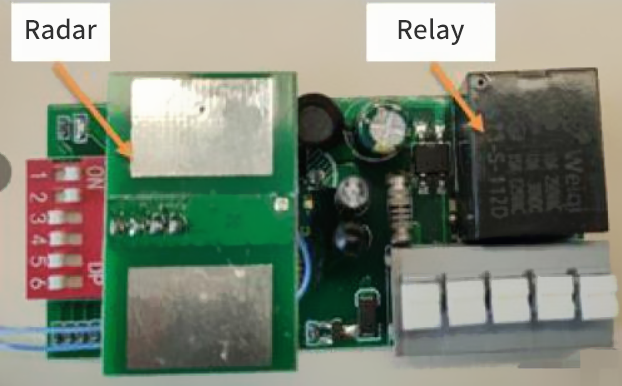
The on/off of the relay creates a strong interference that affects the radar signal. How do customer solve this issues?
The on/off of the relay creates a large interference in the power supply.Meanwhile the relay metal shrapnel's movement is a Doppler interference, which needs to be handled accordingly by the module hardware and software:
a.When designing the product structure, put the radar sensor far away from the relay position, or do a shielding on the structure, as follows:

b.The terminal software shields the relay interference and ignores the radar sensing signals at the moment when the relay is turned on and off.
Q
In the case of dense distribution, each radar sensor may interfere and cause false triggering. Use attention as follows:
a. When radar sensors are densely distributed, the antennas of the radar should be ensured to be parallel to each other as far as possible to avoid facing illumination. For scenes requiring dense distribution such as aging test, the distance between each lamp should be ensured to be more than 20cm;
B. For scenarios where radar antennas may illuminate each other, it is recommended that the installation spacing exceeds 1m;
Q
The microwave signal will be strongly reflected when it encounters metal, and this signal will introduce additional noise to the radar. Please kindly check more details from the answer:
The microwave signal will be strongly reflected when it encounters metal, and this signal will introduce additional noise to the radar. At the same time, the metal will change the radiation characteristics of the antenna, making the sensing distance change, so the module needs to pay special attention to the following 4 points when it is installed:
a. When the product is designed, the front of the antenna can not be covered by metal material shell or parts.
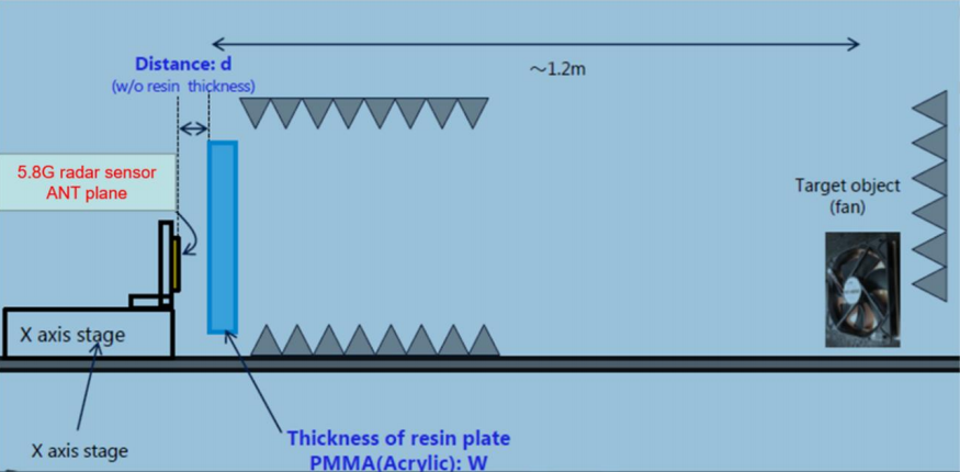
b.It is allowed to have some coverings such as plastic or plexiglass, but the coverings should not be close to the antenna, as shown in the following figure, it is recommended that the distance from the radar module antenna to the finished shell d>3.5mm; the optimal thickness of the shell W<4mm (Note: every 3mm increase in thickness, the sensitivity will be reduced by about 20%);
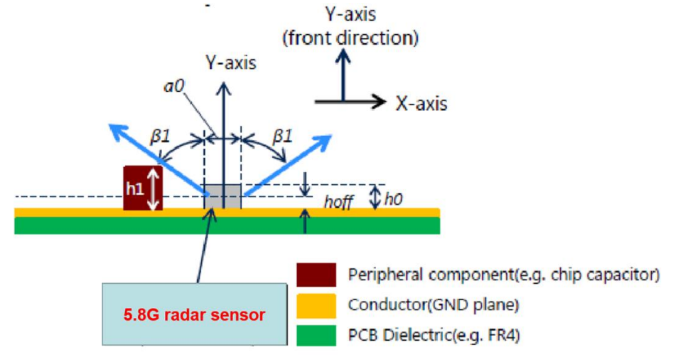
c. When the sensor is installed on the finished product, if there is a metal structure due to the product characteristics and it can not be avoided, please pay attention to the metal structure which can not protrude too much.It is recommended that the components or metal structures and the antenna radiation angle β1> 60 degrees (very important!!!) to avoid sensing the blind spot, as shown in the figure below.The antenna plane of the radar sensor is recommended to be higher than other nearby ground planes h0>5mm.
d. Avoid orienting the radar antenna to face large metal equipment or piping.
Q
The rectifier bridge driven by the power supply has a frequency mixing effect,the industrial frequency signals are easily superimposed on the radar signals and software can be processed separately as follows
a. For the bulb, T8 and other power drive and radar module integration of products, it will be placed in the rectifier circuit away from the radar position in the power supply design, done a good shielding in the overall structural design as shown in the figure below:
b. Software algorithms can be filtered for industrial frequency, and specific software versions are required for scenes with strong industrial frequency interference;
Contact MoreSense Team
Our experts will contact you within 12 hours to discuss your projects needs.

Free service hotline
Contact Mailbox